Did you know slips, trips and falls are some of the most common home safety hazards? Say goodbye to stubbed toes and bruised shins. Add a four-way switch and walk with confidence.
A full day
Intermediate
$50-100
Introduction
Switches are one of the simplest electrical devices. When closed, current passes through it and a light, appliance or device turns on. When you open the switch, current has nowhere to go and the light goes off.
Wiring switches can be confusing, especially with three-way and four-way switches. Three-way switches control light(s) from two locations, like the top and bottom of a stairway. When you add a four-way switch into the circuit, you can control light(s) from three locations, like the entrance to a big family room with three doors from the kitchen, the hall and the back porch.
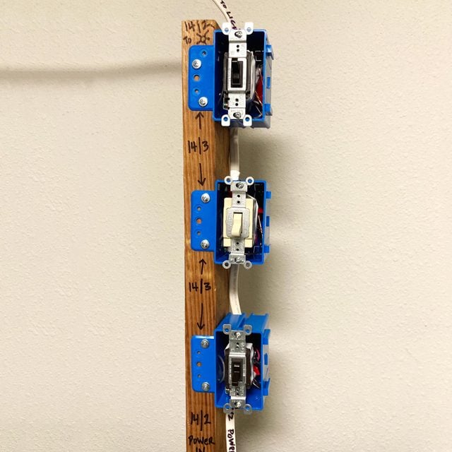
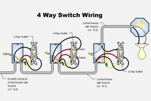
Here we'll show you how to wire a four-way switch. Four-way switches must be installed into the circuit in between two separate three-way switches. We brought power to the first three-way switch box, which is common, but other configurations exist.
Before starting any electrical project, plan your circuitry and the best route for cables. Type NM cable (nonmettallic sheathed) is expensive, so do some homework and make sure you buy the correct size and quantity of cable. And, most importantly, make sure power is off by testing all circuits with a non-contact voltage tester.
Always consult a licensed electrician if you need help. Safety first; this project is not for a novice DIYer.
Tools Required
- Lineman's pliers
- Standard screwdriver
- Utility knife
- Wire strippers
Materials Required
- 14/2 with ground nonmetallic-sheathed cable
- 14/3 with ground nonmetallic-sheathed cable
- 3-way switch (2)
- 4-way switch
- Electrical tape
- Single-gang box (3)
- Wire nuts
Note: this is a complicated wiring setup that requires a solid understanding of basic home electronics.
Project step-by-step (6)
Step 1
Pull Cables to Switch Locations
Bring these cables to your switch boxes and light(s):
- 14/2 (black, white, ground) from panel to first three-way switch.
- 14/3 (black, red, white, ground) from first three-way switch to four-way switch.
- 14/3 (black, red, white, ground) from four-way switch to second three-way switch.
- 14/2 (black, white, ground) from second three-way switch to light(s).
Remember, four-way switches only work if they’re installed in the circuit in between two three-way switches. You can have as many intervening four-way switches as you want in the lighting control circuit, but they have to be bookended by two three-way switches.
Always know what you’re working on. Is it a circuit rated at 15 amperes? Is it a 20 amp circuit? The size of the circuit breaker in the electrical panel determines the rating of the branch circuit.
Here we have a branch circuit originating at a 15 amp circuit breaker, with 14 American Wire Gauge (AWG) cable and light switches rated at 15 amps. Whenever you replace existing light switches, make sure the replacement switches have the same rating.
Step 2
Prep the Cables
- Cut three six-inch pieces of copper grounding wire from a scrap piece of 14-gauge cable.
- These are called pigtails and they’re handy. A pigtail is used when splicing several grounding wires together in a switch box, but where you only have one green grounding screw terminal on the light switch. For safety, light switches must be connected to an equipment grounding wire.
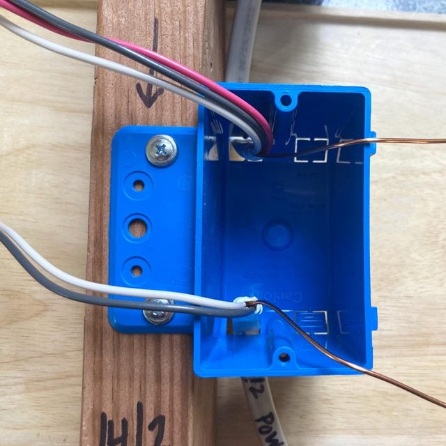
- Remove the exterior sheath from the NM cables inside your switch boxes.
- Leave at least six inches of wire in box to work with. Be generous, but not so much that the wires and switches won’t fit in the box.
- With lineman’s pliers, take the two bare grounding wires in each box and twist them together with a grounding pigtail. Trim off any uneven ends of the wires.
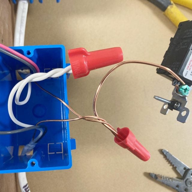
- Spin on a wire nut until tight.
- Make a hook in the free end of the pigtail with wire strippers or needle-nose pliers.
- The hook will wrap around the screw terminal in the same clockwise rotation when tightening the screw.
Step 3
Wire First Three-Way
- Attach the hooked end of the grounding pigtail clockwise around the green screw terminal and tighten with a screwdriver.
- Splice neutral wires (white wires) together and push to the back of the box.
- The National Electrical Code (NEC) requires neutral wires to be installed at switch box locations for connection to electronic devices like dimmers, occupancy sensors, night lights and other lighting controls. Here, the basic three-way and four-way switches do not need a connection to the white neutral wire.
- When splicing, twist together wires and trim off any uneven ends with lineman’s pliers before spinning on a wire nut.
- Attach the black wire from the 14/2 cable (from the power source) to the black, or common, screw terminal on the switch. The common screw terminal is usually identified as a different color than the two “traveler” terminal screws.
- Attach the black and red wires, called travelers, from the 14/3 cable to the brass screws, one wire on each screw terminal.
- Travelers carry current between switches, depending on which switch contacts are activated internally within the body of the switch.
- Hook each wire around the screw clockwise and tighten.
Step 4
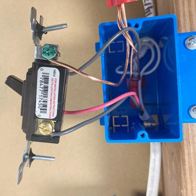
Wire the Four-Way
- Splice the grounding wires together as before and attach the grounding pigtail to the green screw on the four-way switch.
- Splice the neutrals together and push them to the back of the box.
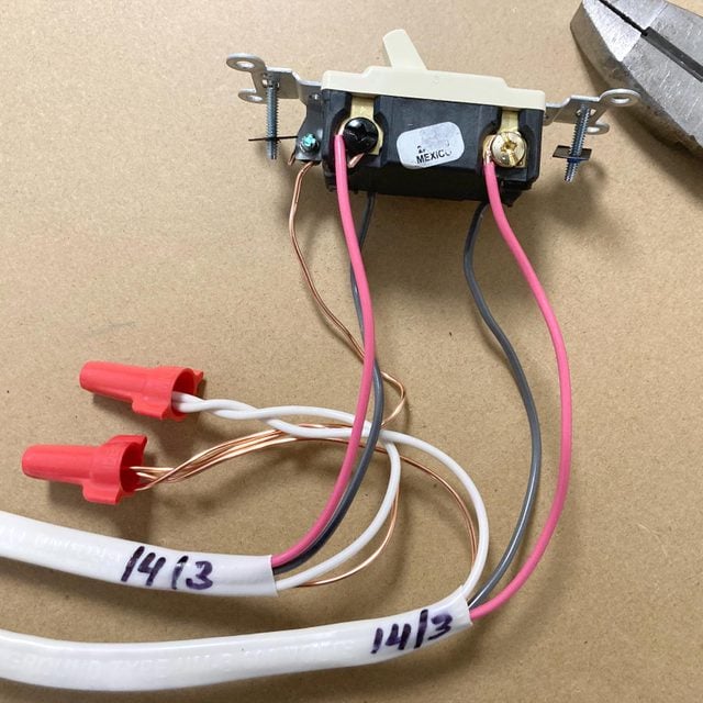
- Attach the black and red traveler wires from the first three-way switch to the terminals labeled “INPUT” or “IN” on the four-way switch.
- Pro tip: Use the screw terminals on the switch, not the holes or “push in” options on the back of the switch. Using the screw terminals is a safer, better connection.
- Attach the other 14/3 black and red traveler wires from the second three-way switch to the “OUTPUT” or “OUT” terminals on the four-way switch.
- When you’re done, the incoming black and red travelers should be connected to the black screw terminals, and the outgoing black and red travelers should be connected to the brass screw terminals.
Step 5
Wire the Second Three-Way
- Repeat Step 3.
- This time, the 14/2 cable will go from the second three-way switch to the light.
- As before, attach the black wire from the 14/2 cable to the common (black) screw terminal on the three-way switch.
- Attach the 14/3 travelers in the same configuration you did on the first three-way switch.
Step 6
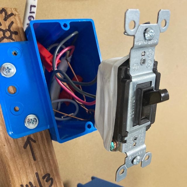
Button Things Up
- Pro tip: It’s always good to wrap electrical tape around the perimeter of the switch and over the screw terminals. The tape helps prevent an inadvertent connection between the grounding wires in the box and the screw terminals on the switch.
- Push switches into boxes and align (level and plumb) the switches before tightening the mounting screws all the way in.
- Attach the switch faceplates.
- At your light location, wire the light with the 14/2 black, white and grounding wires.
- Back at the electrical panel, wire the breaker or call a licensed electrician to bring power to your new switches.