
GFCI Plug Receptacle: How to Install GFCI Outlets
Updated: Feb. 07, 2024
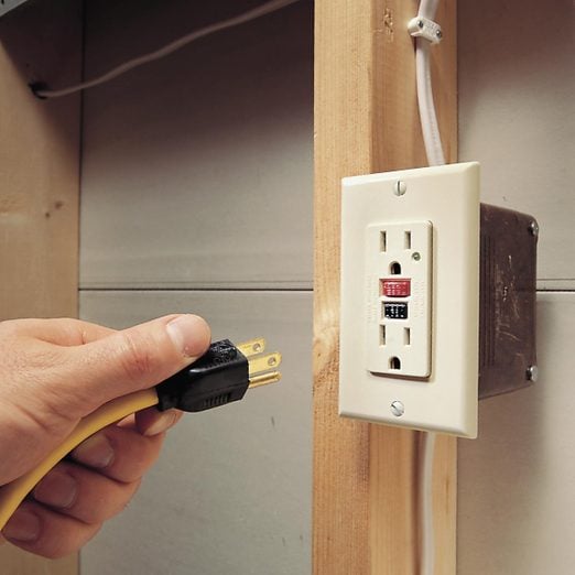
GCFI outlets provide cheap insurance against deadly shocks.
A full day
Beginner
Less than $20
Introduction
Installing a GFCI outlet doesn't have to be confusing. Follow these steps and photos to install a GFCI without getting line and load connections confused.Tools Required
- 4-in-1 screwdriver
- Electrical tape
- Needle-nose pliers
- Non-contact voltage tester
- Utility knife
- Voltage tester
- Wire stripper/cutter
Materials Required
- Electrical boxes
- Electrical cable
- GFCI outlet
- Wire nuts
- Wire staples
GFCI outlets reduce the danger of deadly shock from faulty plug-in cords and devices. A GFCI (ground fault circuit interrupter) is a special type of outlet that detects dangerous ground faults and immediately turns off the power to stop shocks. You can replace almost any electrical outlet with a GFCI outlet. Correctly wired GFCIs will also protect other outlets on the same circuit.
While it’s common to find GFCI outlets in bathrooms and kitchens, there are GFCI outlet requirements. The electrical code also requires GFCIs in unfinished basements, garages, most outdoor receptacles and places where construction activity occurs. We’ll show you how to replace a standard duplex receptacle with a GFCI and wire it to protect other outlets. (For more information about wiring outlets, see Wiring Switches and Outlets).
Project step-by-step (5)
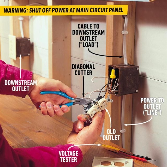
Turn Off Power at the Main Circuit
- Locate the circuit breaker or fuse that controls the outlet you plan to replace and shut off the power to the circuit.
- Plug a lamp, radio or the GFCI tester into the outlet to test for power and make sure it’s off.
Remove the Old Outlet
- Disconnect the wires by clipping them close to the outlet.
- Note: Make sure you know the difference between line vs load GFCI, as shown in the photo.
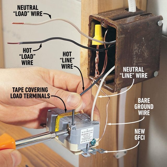
Strip the Wires
- Strip the insulation from the wires to expose the amount of wire shown on the stripping gauge located on the back of the GFCI plug receptacle.
- Connect the hot and neutral wires that provide power to the “line” terminals of the GFCI plug.
- Note: The terminal for the neutral wire will be marked “white” or “neutral.”
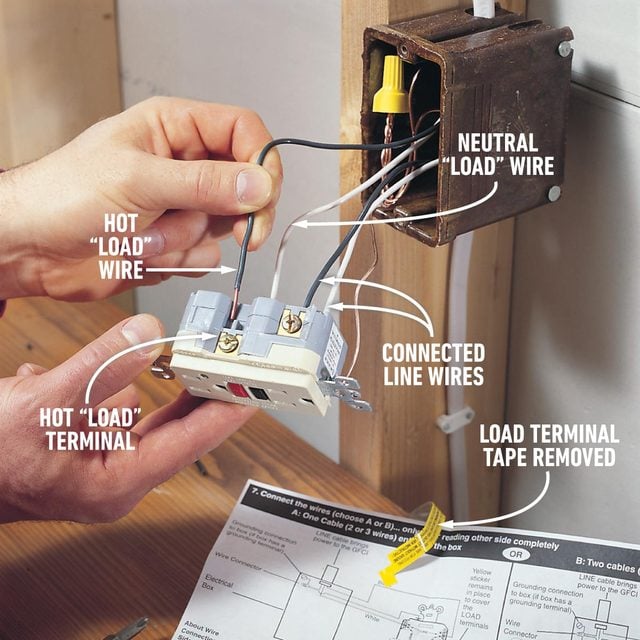
Connect Other Outlets
- Remove the tape covering the “load” terminals and connect the wires leading to another outlet or outlets to these terminals.
- Note: The white neutral terminal will be marked.
- Fold the wires back into the box and screw on the GFCI receptacle and cover plate.
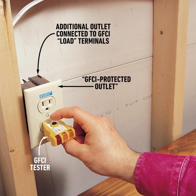
Label the Outlets
- Attach the “GFCI-protected outlet” label to downstream outlets.
- Test the downstream outlet by plugging in the GFCI tester and pressing the test button.
- Note: The lights on the tester should go out.
- Press the reset button on the GFCI to reenergize the outlet.
Check Required Box Size
When you pull out the old outlet, count the number of wires in the box. Calculate the minimum box size required for all of the wires plus the GFCI. If the existing box is large enough, follow the steps above to replace the outlet with a GFCI. If it’s too small, buy a larger box before proceeding.
To figure the minimum box size required by the National Electrical Code, add:
1 – for each hot and neutral wire entering the box
1 – for all of the ground wires combined
1 – for all of the cable clamps combined (if any)
2 – for each device (switch or outlet—but not light fixtures)
Multiply the total by 2 for 14-gauge wire and 2.25 for 12-gauge wire to get the minimum box size required in cubic inches. Plastic boxes have their volume stamped inside. Steel box capacities are listed in the electrical code.
For more information on box replacement, see What You Should Do With Crowded Electrical Boxes.