
How to Install Surface-Mounted Wiring and Conduit
Updated: Feb. 09, 2024
Adding a new light or receptacle to your garage or basement is easier than you think.
Multiple Days
Intermediate
Varies
Introduction
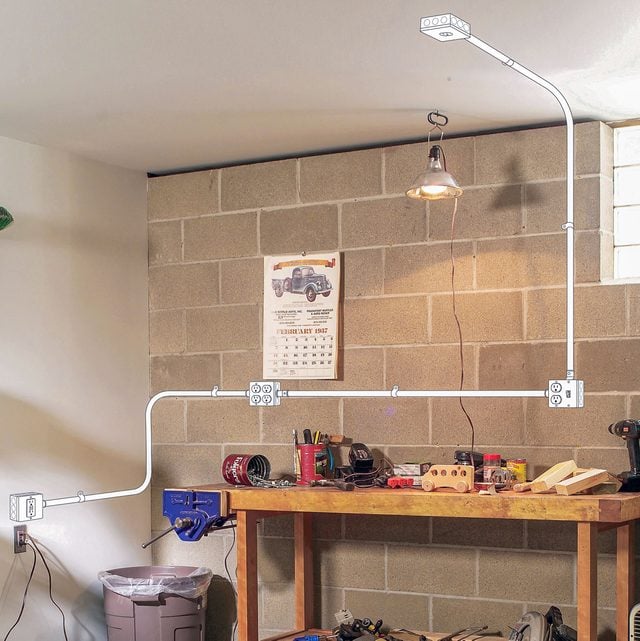
If you're dragging extension cords across your basement or garage to power shop lights and tools, consider extending an existing circuit instead by installing surface-mounted wiring and conduit.
No need to rip up the whole wall or fish wires through the studs. Choose a power source like a wall receptacle and run electrical metallic tubing (EMT) right on the wall to your new basement or garage workbench.
If that sounds straightforward, it is, but you have to do things right. The National Electrical Code (NEC) has multiple requirements for extending circuits, and you also need to worry about electrical loads. I'm a licensed electrician, and we spend years learning how to safely assess electrical additions. So before you start on a project like this, assess your skill and comfort level, and ask for help if needed.
But if you're a handy DIYer and take necessary safety precautions, adding a receptacle or two to your garage or basement is a doable task. Before starting, check with your local electrical inspector to make sure you understand specific local code requirements, and get a permit and inspection, if required.
Below, I'll walk you through the basics of adding surface-mounted wiring to your garage or basement.
Tools Required
- Cordless drill
- Hacksaw
- Non-contact voltage tester
- Wire stripper/cutter
Materials Required
- 1/2-in. couplings
- 1/2-in. offset setscrew connectors
- 1/2" EMT conduit
- 12-gauge (for 20 AMP) or 14-gauge (for 15 AMP) THHN wiring
- 15-amp switch
- 3/4" x 24" threaded water pipe (handle for conduit bender)
- 4 x 4 x 1-1/2 in. metal boxes
- 4-in. square raised covers
- Anchors and screws (for masonry walls)
- Conduit straps
- Receptacles
Project step-by-step (10)
Plan for power
Before you buy a single stick of pipe or measure for your new bench or workspace, work out a plan. Will you be running power-hungry tools like circular saws, routers or table saws? Tap into an existing 20-amp circuit, or add one at your electrical panel.
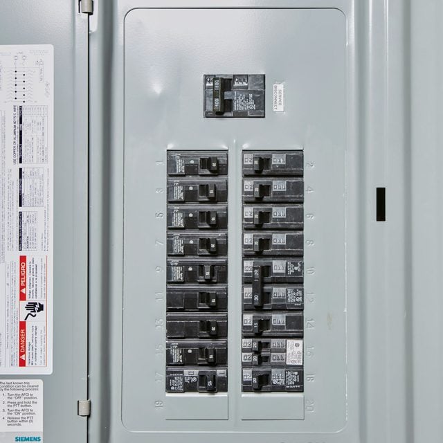
For LED lamps or light-duty tools, a 15-amp circuit should suffice. Check the circuit breaker in the main electrical panel to determine your circuit sizes. If you’re uncertain, consult a licensed electrician.
For this project, we tapped in to a 15-amp garage outlet to power our light duty workbench area. This circuit will handle lights and other continuous loads, as well as tools and other temporarily running devices. For safety, limit the electrical load on a 15-amp circuit to 1,440 watts (12 amps), and 1,920 watts (16 amps) for a 20-amp circuit.
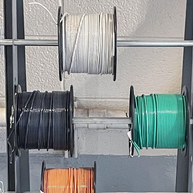
We’re using 14-gauge THHN electrical conductors. (For 20-amp circuits, go with 12-gauge wire.) You’ll need a hot, neutral and green ground wire, aka an equipment grounding conductor.
The EMT can serve as the equipment ground, but I recommend pulling a separate wire to be absolutely sure you have a continuous path back to the panel in the event of a short circuit or ground fault.
Lay out your run
Sketch the electric conduit route from your power source to the new electrical box locations. Use a pencil and paper, a software program or just mark the wall with painter’s tape to visualize the layout of your new design.
Start from the power source (in our case, the wall receptacle) and mark where your new boxes will go. Unless you’re a skilled pipe bender, minimize bends as much as you can.
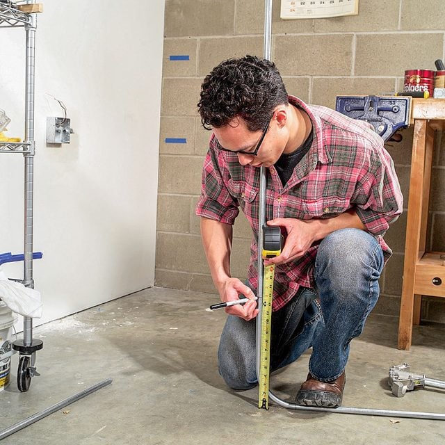
When you have the basic layout, grab a measuring tape and figure out how much pipe and wire you’ll need to buy. Measure between boxes, including the vertical rise, and add several feet to your final total so you have plenty to work with.
Buy an extra stick or two of EMT in case you mess up, and make sure you have enough excess wire length to leave six inches in every box. I like to leave eight inches or so and cut it off.
In addition to the EMT and electrical boxes, you’ll need set screw connectors to secure the EMT to the boxes, straps or hangers to hold the pipes to the wall, and couplings to connect longer runs. And, of course, various hardware and hand tools.
When you calculate the length of your run, also count the number of fittings, boxes, receptacles and industrial box covers needed for your project.
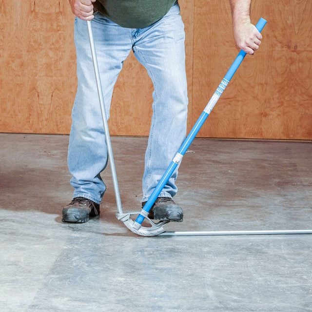
Bending basics
Bending 1/2-in. EMT isn’t hard, but it takes finesse. You’ll need a specialty tool called a conduit bender to make the 90-degree angles necessary to turn corners or change directions. Or you can purchase pre-made 90-degree elbows and connect them to the straight runs with couplings. Either way is fine, but for a more professional look, use a bender.
I’ll show you how to make 90-degree bends, since they’re the easiest and most often used.
Another common bend is an offset, a two-part bend used to lift the conduit off the wall slightly as it enters an electrical box. This is a much more difficult bend, especially for a beginner, so save yourself frustration (and money) and use conduit hangers, aka “minnies,” to strap your EMT to the wall. These straps hold the EMT just off the wall enough to go straight into the box without an offset.
Another option: Using offset connectors to link the EMT to the box. These allow you to hang the EMT flush to the wall and use the connector as the offset instead of the pipe. These would not be my choice, because they’re hard to pull wire through and they just don’t look as nice as offset bends or even minnies. But if that’s not a deal-breaker, go ahead!
Turn off the power
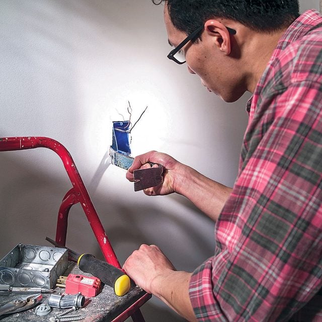
Test your non-contact voltage tester on a known live circuit, like a cord or kitchen receptacle that’s powered. If it beeps, your tester is working. Then turn off the power to your receptacle by flipping the corresponding breaker in your electrical panel.
Stick the tester in the slots of the receptacle to check for power. Carefully remove the faceplate. Test every contact point on the existing receptacle, then remove the screws and gently pull it out.
Stick the tester deep into the box to check every single wire in there. You may have more than one circuit in the box, so if you hear any beeping, turn off individual breakers until the entire box is dead. Remove the receptacle from the box.
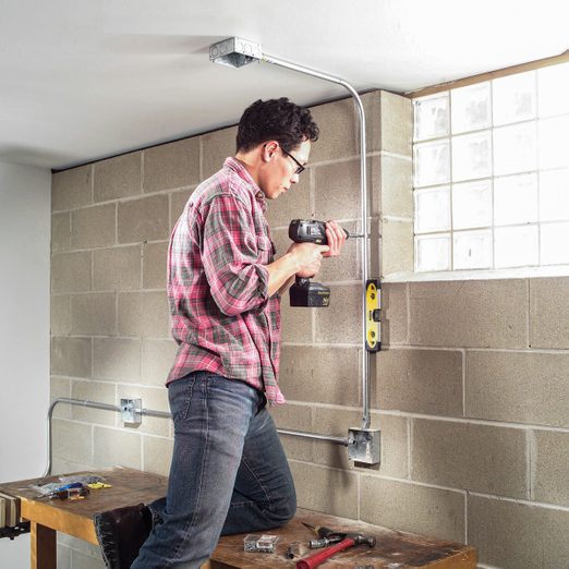
Start at the power source
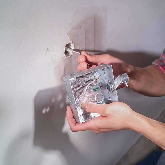
Always work from the power source to the end of your pipe run. That way, you always have an “open” end of the conduit for adding boxes and fittings. (It’s really hard to jam a piece of pipe in between existing, attached boxes.) Remove the existing box from the stud. If you have extra Romex in the wall, great! Pull it through the hole.
If the cable is too short to reach a surface box with at least six inches of conductor to work with, determine the direction the Romex is coming from in the wall and cut away the drywall slightly until you have enough cable to pull through the back of the box. Make sure you will have 1/2-inch or so of the plastic sheathing inside the box.
Or cut a small hole about six inches above or below the existing opening, and pull the Romex through. Patch the drywall before proceeding, if it will interfere with attaching your new box.
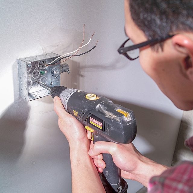
Remove one of the 1/2-in. metal “knockouts” in the back of the box and add a cable clamp. Knock out one of the holes on the side for your EMT, and add a set screw connector. Mount the box to the wall by driving two 1-5/8-in. drywall screws through the drywall and into the stud. Keep the box level.
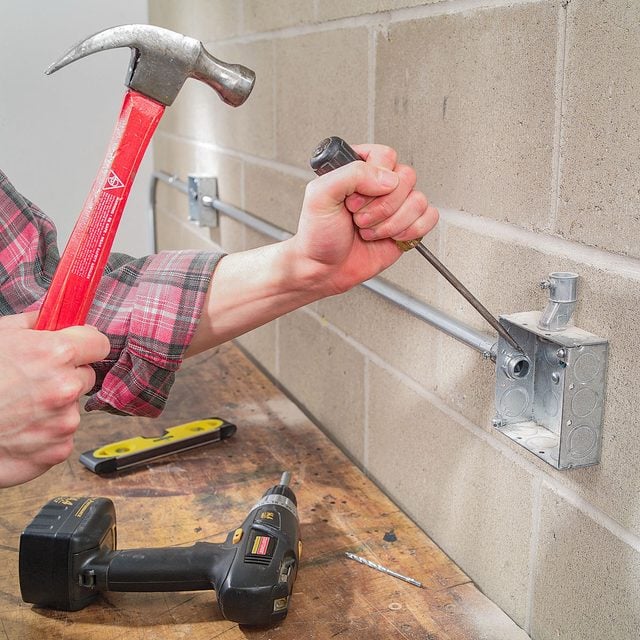
Bending conduit
Half-inch EMT is forgiving, But for a beginner, making two direction-changing 90-degree bends in one stick of pipe may be difficult. You may end up with the second bend going the wrong direction or otherwise looking a little wonky. To quote myself: “That’s why we have couplings.”
If you follow these next directions and it doesn’t work out, just cut the pipe in between your 90-degree bends and use a coupling to fit them together in the right orientation on the wall.
Measure from the wall corner to the edge of the box and subtract a quarter inch. (Alternatively, measure to the “shoulder” of the connector.) Subtract five inches, which is the “deduct” for a 1/2-inch bender and accommodates the sweep of the bend. Then subtract a half inch to accommodate the conduit hanger that will be on the other wall.
Example: If your measurement was 33-1/2-inches from the corner to the shoulder, mark your pipe at 28 inches.
How to bend the pipe
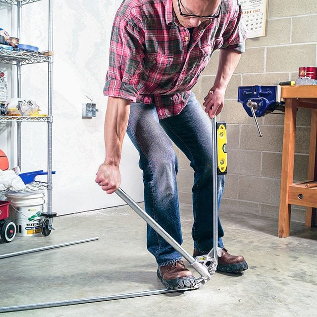
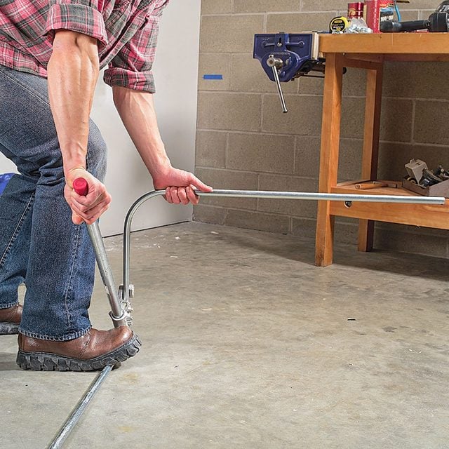
Slide the pipe into the bender and align your mark on the arrow. The longer end of the pipe should be sticking out the side with the foot pedal. Have your torpedo level in your pocket. Put your foot on the pedal and push down on the bender handle. Keep your foot pressure steady! If you let up your foot, it may kink the pipe.
The stub end of the pipe will pop up and form an angle. Holding your foot steady, stick your torpedo level on the pipe and stop bending when it’s 90 degrees and level. Going a little over is fine. It’s easy to manipulate 1/2-inch pipe. Not to mention that walls, especially garage or basement walls, aren’t always plumb. Hold the bend up to your corner and check to see that it fits.
Measure the rise (height difference) between your first box and where you want your next one to be. Subtract the five-inch deduct, then add back three-quarters of an inch to account for the height of the conduit in the first bend.
Measure from the stub end (put it flat against a wall or floor) and make a new mark on your conduit. Slide the pipe into the bender, again with the straight end of the pipe sticking out the foot pedal side and with your mark on the arrow.
Here’s where it gets tricky. Before you make that second bend, the first stub must be level with the ground and pointing the “right” way, depending on the direction you want to turn.
Remember, the first bend is the bottom one on the wall, but while you bend the second 90, it’s on top. Visualizing which way the bends will orient when you flip the pipe into position on the wall may help. If not, try again, or cut the pipe and plan to use a coupling.
Add supports and other boxes
Stick the pipe in the first connector, hold it level and in position and mark where your conduit hangers will go. You must have a hanger within three feet of each box and every ten feet in between.
Remove the pipe. Attach the minnies to a stud, or use drywall anchors. If you’ve made cuts to your conduit, remove the burrs by rubbing your pliers along the edges and inside until there are no sharp points that could snag an electrical wire.
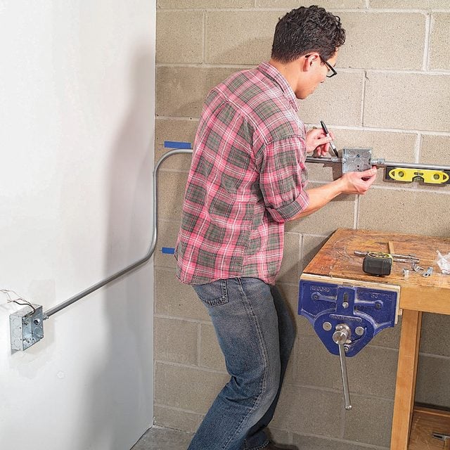
Stick the pipe in the connector and minnies. Level pipe and tighten minnies as you go. Add your second box to the end of the pipe (cut to length if needed), or add a straight piece to reach your destination.
Level the box and mark anchor holes or drive screws into the stud. For masonry walls, use plastic anchors, and don’t forget to drill a small hole to accommodate the ground screw. Repeat these steps for your other boxes.
Tighten set screws and minnies and go through every box and tighten the connector locknuts by rapping on them with a screwdriver and hammer. This is critical. All non-current carrying metal parts of your installation must be connected, or bonded, for safety and code compliance.
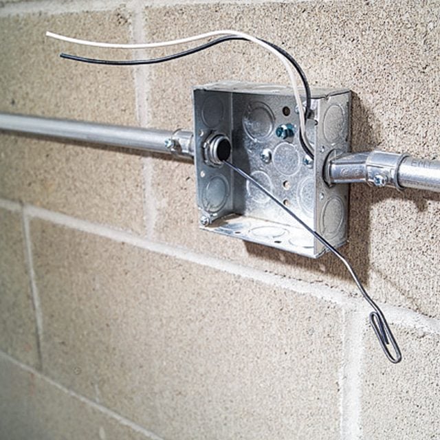
Running the wire
If your run is uncomplicated, just tape your black, white and ground wires together and push them through the pipe. Make a loop in one end of one wire to make it easier to maneuver through couplings and bends. For longer runs or several bends, use a fish tape. Leave eight inches or more of excess length at each box so you can wire your receptacles.
Garage and basement receptacles must be GFCI protected, and this can be accomplished by a GFCI breaker or a GFCI receptacle that protects the rest of the circuit.
If you already have a GFCI breaker or receptacle protecting the circuit, you can use regular 15-amp, tamper-resistant receptacles for this project. If not, break off the ears of your GFCI receptacle so it will fit in the first box and screw into the industrial cover.
Follow the wiring instructions on your devices — the power supply goes around the “line” terminal screws (don’t use the push-ins), and the downstream wires go on the load side (remove the yellow tape).
Connect the ground screw on the receptacle, the ground screw on the electrical box (use a pigtail) and the green equipment grounding conductor together at each box.
As always, consult a licensed electrician if you need help.
FAQs
Is surface wiring legal?
Yes, but not all locations have the same rules for damage protection, or allowable wiring methods and raceways. Consult a licensed electrician for specifics if your installation varies from this one.
Is surface wiring cheaper?
It can be. Conduit, boxes, fittings and your labor cost money, but the alternative (opening up the wall) has its own cost considerations.
How much does it cost to wire a 2,000-sq.-ft. house?
It depends. Material and labor costs vary widely across the country, as do aesthetic or optional choices by homeowners. According to HomeGuide’s tracking of millions of contractor estimates, the average is $6 to $9 per square foot, or $8,000 to $18,000 for a 2,000-sq.-ft. house.
Sources
- National Fire Protection Association, NFPA 70: National Electrical Code, 2023 edition.
- HomeGuide: Electrical wiring installation cost for new house construction, April 2023