
How to Rough-In Electrical Wiring
Updated: Dec. 07, 2023
Do-it-yourself guide with professional techniques for a safe wiring job.
Multiple Days
Intermediate
$51–100
Introduction
You can save a lot of money by doing your own wiring. Here we'll show you to wire an entire room. Even if you've never picked up an electrical tool in your life, you can safely rough-in wiring by following the directions in this article. You'll learn all of the pro techniques for a wiring job, including choosing the right size receptacle boxes, running cable throughout the room, and making the electrical connections.Tools Required
- Drill/driver - cordless
- Hammer
- Tape measure
Plastic boxes and flexible nonmetallic cable (commonly called Romex) put electrical wiring projects within the skill range of every dedicated DIYer. In this article, we’ll show you some house wiring basics—how to position outlet and switch boxes and run the electrical cable between them. We won’t cover many other house wiring details. For help with circuit design and making connections to your main electrical panel, we recommend you consult a licensed electrician. Here’s your guide to garage wiring.
Need help deciding whether to DIY or hire an electrician? Find out how much an electrician costs.
Besides standard hand tools, you’ll need a special-purpose tool to cut and strip electric wire. We like the Klein No. 1412 ($18 at hardware stores and home centers). To drill a few holes, use a 3/4-inch spade bit in your electric drill. For larger jobs, rent a heavy-duty right angle drill ($25 per day) and equip it with a 3/4-inch x 6-inch auger bit ($7).
Electrical house wiring mistakes can be deadly, so make sure you obtain a permit from your local building department and have an electrical rough-in inspection scheduled with a building official when you’re finished. Draw a sketch of your room that shows lighting, switch and outlet locations. Review your plan with the inspector and ask whether there are any special requirements.
Be safe! Here are the top electrical mistakes to avoid:
Project step-by-step (13)
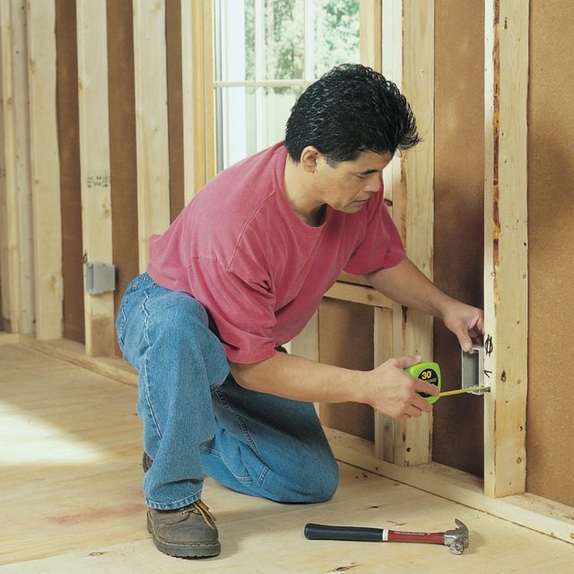
Mark the Box Locations
- Measure and mark the center of each box.
- Mark the height from the floor to the center of the boxes (usually 48 in. for switches and 12 in. for outlets) or line them up with existing boxes to determine electrical outlet height.
- Use letters and symbols to identify boxes.
- Add 2×4 blocks to position boxes away from wide window and door trim.
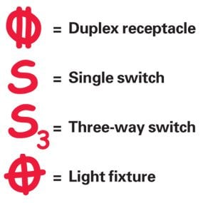
Mark Box Location with These Symbols
- Mark the box locations on the studs using symbols to indicate outlets, switches and lights.
Place the Box on the Framing Member
- Position the box so its face will be flush with the wall covering material.
- Nail the box to the framing.
- Pro tip: Double-check that the face of the box is parallel with the framing member.
Calculating Box Sizes
The electrical code limits how many wires you can safely put in an electrical box. To figure the minimum box size required by the National Electrical Code, add:
1 – for each hot and neutral wire entering the box
1 – for all the ground wires combined
1 – for all the cable clamps combined (if any)
2 – for each device (switch or outlet-but not light fixtures)
Multiply the total by 2 for 14-gauge wire and 2.25 for 12-gauge wire to get the minimum box size required in cubic inches. Plastic boxes have their volume stamped inside. Steel box capacities are listed in the electrical code.
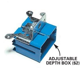
Most boxes have nibs or marks to help you align the box for use with standard 1/2-in. thick drywall. If you’re not sure how thick the final wall material will be, use a special adjustable depth box.
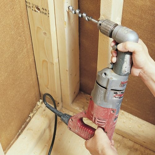
Drill Holes in the Framing
- Bore 3/4-inch holes through the framing members about 8 inches above the boxes.
- Pro tip: Center the bit on the stud, brace the drill and apply pressure with your thigh for easier drilling of wall studs.

Drill into Corners at an Angle
- Angle the bit into tight spots.
- Make sure there’s at least 1-1/4 inches between the back face of the stud and the cable.
- Cover the face of the stud with a metal nail plate to protect the cable where the hole is closer than 1-1/4 inches to the face of the stud.
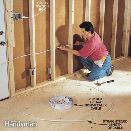
Thread the Cable Through the Holes
- Straighten about 12 feet of cable and thread it through the holes from one box to the next.
- When you reach each new box, follow the stripping procedure shown below, and push the conductors and about 1/4 inch of sheathed cable into the box.
- Staple the cable.
- Cut the end still connected to the coil and repeat the process at the other box.

Run the Cable Around Corners
- Fish the cable around corners by bending a sharp hook in it.
- Stick your little finger into the hole to feel for the cable and guide it through as you apply pressure with the other hand.

Cut the Cable at the Box
- Grab the cable at the point you estimate it will enter the box.
- Cut the cable about 12 inches beyond this spot and strip off all but about 1 inch of sheathing.

Knock Out a Hole in the Box
- Punch a hole (or two for two cables) through the knockout area of the box with a screwdriver or the point on your stripping tool.
- Push the conductors and about 1/4 inch of sheathed cable into the box and staple the cable within 8 inches of the box.
- Note: The cable must be at least 1-1/4 inch from the face of the framing.
- Push the first cable aside while you staple the second cable.

Run Cables to the Main Service Panel
- Run cable(s) from your completed circuits to the service panel.
- Pro tip: Leave 4 extra feet of cable for the electrician to work with.
- Label the cables with the location of the circuit.
- Call in the electrician to connect the circuits.

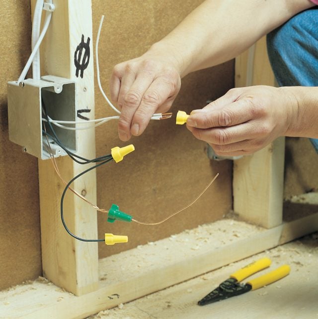
Cut and Strip the Wires
- Cut all the wires to leave at least 6 inches protruding past the face of the box.
- Leave one bare copper ground wire an extra 6 inches long.
- Thread the long ground wire through the hole in the top of the special green wire connector and splice all the ground wires by holding them together and twisting the connector clockwise until it’s tight.
- Strip the ends of the white and black wires and one end of each 6-inch-long pigtail.
- Splice them with wire connectors.
- Cover the unstripped end of the black (hot) pigtail with a wire connector for safety.
Group the Wires Together
- Group and label the wires in the switch boxes so you’ll know how to connect them after the drywall is complete.

Push the Wires into the Box
- Fold and pack the wires neatly into the box to conserve space and reduce pressure on connections.
- Label wires with scraps of cable sheathing. Electrical plans are a roadmap to project success. And, yes — you can draw your own!
