
Showcase Built-In Bookcase Plans
Updated: Mar. 19, 2024Turn a bland wall into a showstopper for $300!

Construct a dramatic built-in bookcase and entertainment center with these simple plans. All you need is some inexpensive lumber and drywall.
- Time
- Complexity
- Cost
- Multiple Days
- Intermediate
- $101–250
About this project
Dramatic results with cheap materials
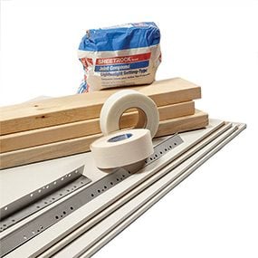
Stunning projects usually carry a stunning price tag. Not this one. It requires only common 2×6 framing lumber, drywall, corner beads and joint compound. All of the materials for this project (not including the lights and wiring) cost us only $300. And you can get everything off-the-shelf at your local home center or hardware store.
There aren’t many DIY projects that will give you as much bang for the buck as this dramatic drywall showcase. Granted, you’ll have a chunk of time invested before you’re done, but the materials are readily available and inexpensive. As you’ll see, it’s just 2×6 framing covered with drywall. And the beauty of this type of construction is that the design is limited only by your imagination. You can build shelves just like ours, or you can design any other size and shape you like. In this article we’ll show you how to build the frame, hang the drywall, and finish the project with corner bead and drywall tape. We’ll also show you how to add an outlet for the TV and wire the switch and lights. Learn more about how to hang and tape drywall and installing outlets and switches.
Our wall is 12 ft. wide with a 9-ft. ceiling. We designed the 18-in.-deep shelves to accommodate home theater gear and the center rectangle to fit around a 60-in. TV screen. This arrangement also looks great even if your ceilings are only 8 ft. high. And keep in mind that you don’t have to build your shelves wall to wall. You can leave one or both ends exposed and simply finish them with drywall.
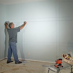
We used a computer drawing program called Sketchup to design these shelves. But you can use graph paper or just map it out on the wall. We first added about 5 in. to the width and height of the TV, and then centered this rectangle on the wall. When we were satisfied with the design, we marked the wall at the vertical and horizontal framing locations and chalked lines to get a better sense of how it would look (Photo 1). We left a 1/2-in. space between the 2×6 framing and the floor, walls and ceiling. The 1/2-in. space serves two purposes. First, it allows you to prebuild the framing and slip it in without trying to fit it exactly to the room. And second, the 1/2-in. space creates a perimeter that’s the same width (6-1/2 in.) as the rest of the vertical and horizontal dividers after they’re covered with drywall.
Getting started
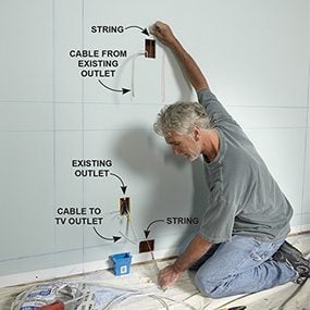
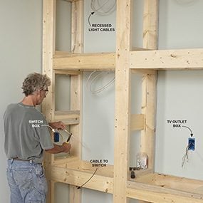
Photo 2: Add a switch and outlet
If your project includes a TV and lights, you’ll need another outlet and a switch. Start by turning off the power to the existing outlet. Cut a hole for the new TV outlet and another hole directly below, near the floor. Extend NM (nonmetallic) electrical cable from the existing outlet to the new TV outlet. Run another cable from the new outlet through the hole near the floor. Leave enough cable to reach your switch location plus at least 12 in. of extra cable (Figure B).
If your room is carpeted, you can either build right over the carpet, or peel it back and hire a carpet layer to reattach it after you’re done. You can cut the baseboard molding in place, or remove it like we did and reinstall it when the shelves are done. Make sure the framing isn’t going to cover an electrical outlet. If it is, you’ll have to relocate the outlet or change your design. We’ve included a Shelf Materials List in Additional Information (below), but you’ll have to adjust the quantities for your design.
Measure the distance from the floor to the ceiling at both ends of your proposed shelves. Then measure the distance between the walls at both the top and the bottom. Subtract 1 in. from the smallest measurement of both the width and the height. Use these dimensions to build the frames.
Build the frames
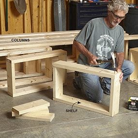
The 2×6 framing consists of a full-length base and top, four vertical columns and shelves. You can build all of the parts in your garage or backyard (Photo 3) and move them into your room to assemble. Cut the 2x6s for the top and bottom to length and mark the column locations. If you have a miter saw, set up a stop and cut all the short crosspieces you’ll need.
You can see from Figure A that you’ll need three crosspieces, assembled into a U-shape at each column location. Use L-shape crosspieces at the ends. Nail the top and bottom frames together. Then build the columns. The center columns have 2×6 boxes at each shelf location to provide backing for the drywall on both sides. We added flatwise 2x6s to provide backing for our glass-shelf supports. Finally, build the shelves.
Figure A: Shelf Framing
The overall dimensions of the built-in bookcase wall are 11′ 11′ wide x 9′ tall x 17-1/2′ deep. For a printable PDF version of this illustration and a complete list of the shelf materials and electrical supplies, see Additional Information, below.
Prepare for wiring
If you’re going to add lights and another outlet, add the new outlet box and the cable that runs to the switch before you install the framing (Photo 2). The first step is to turn off the power to the outlet, and double-check that the power is off by testing the wires with a noncontact voltage detector. Then remove the outlet and twist wire connectors onto the black wires as an extra precaution. Determine whether the wires are 12 or 14 gauge. Then count the wires in the box and calculate the box size required, including the extra hot, neutral and ground wire you’ll be adding. For information on calculating box sizes, check out How to Install a Dimmer Switch. If the box is too small, cut it out and add a larger one.
Remove a knockout from the top of the box for the new cable. If the box is metal and doesn’t include built-in cable connectors, add a cable connector to the new cable. Next, cut the hole for the TV outlet. To make running new cable much easier, try to choose a location that’s in the same stud space as the existing outlet. If this isn’t possible, you’ll have to cut out some drywall to drill through studs. Mark around the remodel box and cut the hole. Also cut a hole near the floor, directly under the TV outlet hole.
Match the gauge of the new cable—12 or 14 gauge—to the gauge of the wire in the existing box. Run the NM (nonmetallic) cable with ground from the existing outlet to the new outlet, and from the new outlet to the hole near the floor. Leave 12 in. of extra cable at the new outlet. Then run enough cable from the new outlet through the hole near the floor to reach your new switch location. Be generous with the cable to the switch to be certain you’ll have at least an extra foot at the switch location. That’s all the wiring you need to do for now.
Install the framing
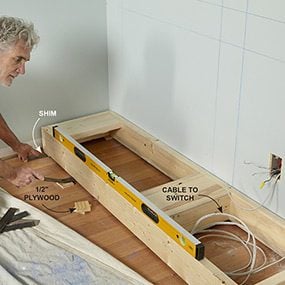
Photo 4: Level the base
Shim the base up with 1/2-in. scraps of plywood on all four corners. Then use a level and add shims as needed to level the frame across the front and from front to back. Add shims under each column. Screw the frame to the wall studs.
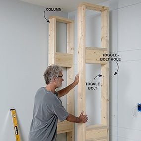
Photo 5: Set the columns
Screw the outside columns to the base. Plumb them and attach them to the wall with screws or drywall anchors. Position the center columns, plumb them and attach them the same way.
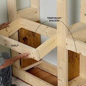
Tack small squares of 1/2-in. plywood to the four corners of the bottom frame. Drill a 3/4-in. hole in the back 2×6 to feed the cable through. Set the frame in place and level it by adding shims if necessary (Photo 4). When the frame is level, add scraps of 1/2-in. plywood and shims under the two column locations. Make sure the frame is centered, with a 1/2-in. space on each end, and screw it to the wall. Next, install the columns (Photo 5). Use a level to make sure the end column is plumb and screw it to the bottom frame and to the wall. If there is no stud to drive screws into, use toggle-type drywall anchors to hold the column against the wall. Then use the shelves as spacers to make sure the columns are in the correct locations before you screw them to the base. There should be a 1/2-in. space between the wall and the end columns.
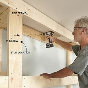
Next, set the top frame in place on the columns. Screw the top frame to the wall, and screw the top of the columns to the top frame (Photo 6). Finish the framing by installing the shelves (Photo 7).
Rough-in the wiring
Before you start your project, contact your local inspections department to find out if an electrical permit is required. In most cases the wiring will need to be inspected before you cover it with drywall. The new electrical code requires an AFCI (arc-fault circuit interrupter) in many areas when new wiring is added. Ask your inspector if an AFCI is required in your situation. If so, simply replace the existing outlet with an AFCI receptacle, and run power from the “load” side of the AFCI outlet to the new TV outlet and then on to the switch and lights. Any new receptacle outlets must also be tamper resistant.
Start wiring by nailing a switch box to the frame in a convenient location, and then drilling 3/4-in. holes through the framing to make a path for the new cables (Photo 8 and Figure B). Run lengths of cable from the TV outlet to the switch, from the switch to the first light fixture, and between the light fixtures. Leave a 2-ft. loop of extra cable at each light fixture location. For more information, see How to Rough-in Electrical Wiring.
We ordered our 3-in. recessed light fixtures online because the fixtures we found at a home center were too tall to fit in the drywall space and still meet the electrical code requirement of 1/2-in. space between the fixture and the combustible surfaces. We chose remodel-type fixtures, which are installed after the drywall is finished. You can choose any non-IC (insulation contact) fixture you like, as long as there’s at least 1/2 in. between the fixture, and any combustible material and insulation are kept more than 3 in. away. You can use any IC-rated fixture that will fit in the space.
When the wiring is in place, call for a rough-in wiring inspection. After the wiring is approved, move on to the drywall and corner bead.
Figure B: Electrical Diagrams
These diagrams illustrate the wiring arrangement used in this project. For a larger version of this diagram, see Additional Information, below.
Cover the frame with drywall
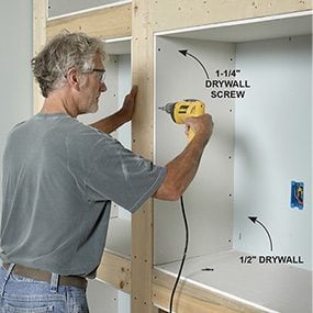
You can cut the drywall the usual way by scoring one side with a utility knife, bending it to break at the scored line, and then cutting the paper backing. But for fast, super-clean cuts, we used a table saw to cut the drywall. We have a table saw with a good dust collection system, so it wasn’t too dusty. But you could also cut the drywall outdoors with a circular saw and a straightedge. Stack four pieces of drywall and cut all of them in one pass. We started by cutting a 2-1/2-in.-wide strip from the edge of each sheet to remove the tapered section. We did this to avoid having a tapered edge under the corner bead or at the back where we wanted to caulk the back edges rather than tape them (Photo 15). If you’re using the score-and-break method, clean up the cut edges with a rasp.
Once the pieces are cut to width, it’s easy to cut them to length and screw them to the framing. Mark the length and use a drywall square to score them. All drywall cuts should be 1/8 in. to 1/4 in. less than the actual measurements. You can easily fill gaps, but drywall will break along the edge if you try to force it in. Attach the drywall with 1-1/4-in. drywall screws. Use a special drywall screw gun, or buy a special bit for your cordless drill that sets the screws just under the surface without driving them too deep.
Nail on the corner bead
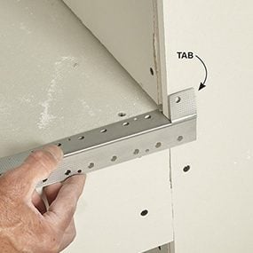
Photo 10: Nail on the top and bottom corner beads
Notch one of the corner beads as shown here. Push it into the corner and mark the opposite end. Notch the other end the same way. Fit the corner bead into the opening and staple or nail it. Repeat on the opposite side of the opening.
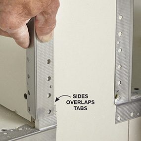
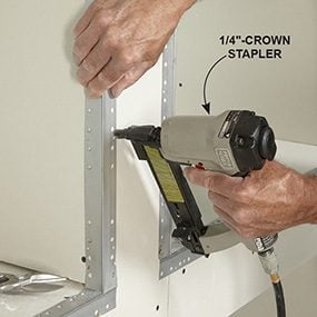
There are several types of corner bead. You can buy perforated plastic corner bead that attaches with spray adhesive, or paper-faced corner bead that you embed in a layer of joint compound. But we decided to use conventional metal corner bead. To speed up the process, we used a 1/4-in.-crown, air-powered stapler to fasten the beads (Photo 12). You can buy a stapler for as little as $30. Or simply fasten the corner bead with 1-1/4- in. ring-shank drywall nails.
You’ll need a tin snips to cut the corner bead. Photos 10 and 11 show an easy method for cutting the metal beads to length and creating a strong corner. The key to installing corner beads is to press them in until the outside corner is just slightly proud of the drywall before driving the fasteners. Also, adjust the position of the bead so the corners of adjoining beads line up. For extra insurance against cracking, cover all the corner bead edges with adhesive-backed mesh tape.
Tape the corners and fill the bead
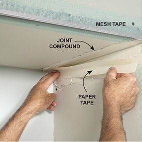
Photo 13: Tape the inside corners
Spread a layer of joint compound on both sides of the corner. Cut a piece of paper tape and fold it to fit in the corner. Press the tape in with your fingers. Then embed it with your taping knife. Spread a thin layer of compound over the top of the tape.
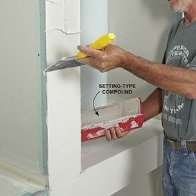
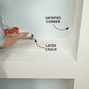
To save time, we decided to confine our taping to the intersection of the sides and tops of the drywall recesses (Photo 13). We caulked the back edges later (Photo 15). Start by taping the inside corners. Then fill the corner beads with joint compound. Use 45-minute setting-type compound for this. Mix the powder with water according to the instructions on the bag. Then use an 8-in. taping knife to fill the corner beads (Photo 14). We used almost two full bags of setting compound for this project. When the joint compound has firmed up to the consistency of soap, carve off any lumps and high spots with your taping knife. You can add another coat as soon as the compound hardens. You don’t have to wait for it to dry completely.
Don’t rush this part of the job. Plan on spending a few hours a day for several days. Use premixed joint compound for the final coats, letting it dry between each coat. Trowel on thin coats until you’ve got a smooth, flat surface. Let the final coat dry. Then sand carefully with 120-grit drywall sandpaper mounted on a drywall sander. Use a fine sanding sponge with an angled edge to sand the inside corners. Vacuum all the dust from the surfaces and check your work with a strong raking light. Fill any imperfections, resand, and you’re ready to prime and paint.
Finish the wiring
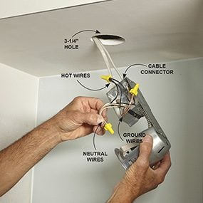
Photo 16: Install the recessed lights
Cut holes for the lights using the template provided, or a large hole saw mounted in a drill (we used a 3-1/4-in. hole saw). Remove the cover and knockouts and add cable connectors if they’re not built into the fixture. Push the cable(s) through the connectors and connect hot, neutral and ground wires with the appropriate wire connectors.
When you’re done sanding the drywall, you can install the recessed lights. Then when the painting is complete, finish the wiring by adding the outlets and connecting the switch or dimmer switch. For more help, see Wiring Outlets and Switches. Figure B shows how to wire the outlets and dimmer switch. Photo 16 shows how to install the recessed lights.
We used 6-watt dimmable LED flood bulbs in our fixtures. If you’re using LED bulbs and want to install a dimmer, check the manufacturer’s instructions to make sure the switch is compatible with the brand of LED bulb you’re using. When the wiring is complete, turn on the circuit breaker to check your work. Then call the electrical inspector for a final inspection.
Finishing touches
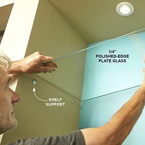
Since we wanted to use the shelves as an entertainment center, we cut holes for low-voltage old-work brackets in the back wall of the TV compartment and the compartment below it. That way we could run HDMI and other audio/video cables through the wall from the components to the TV. Make sure the cables are rated for in-wall use—look for CL2- or CL3-rated cables.
We also installed 1/4-in. polished-edge plate-glass shelves in two compartments (Photo 17). To protect the drywall from wear and moisture (such as from potted plants), consider having more glass pieces cut that you can use to cover the bottoms of the other compartments. Reinstall the baseboard molding and you’re ready to move in and enjoy your dramatic new display wall.
Additional Information
Required Tools for this Project
Have the necessary tools for this DIY project lined up before you start—you’ll save time and frustration.
- Air compressor
- Air hose
- Caulk gun
- Cordless drill
- Dust mask
- Non-contact voltage tester
- Paintbrush
- Roller sleeve
- Roller tray
- Safety glasses
- Shop vacuum
- T-square
- Taping knife
- Tin snips
- Wire stripper/cutter
Required Materials for this Project
Avoid last-minute shopping trips by having all your materials ready ahead of time. Here’s a list.
- See Materials List in "Additional Information"
